Installing markers on control panel wiring follows one sequence: print the full legend set from the schematic before cutting any wire, slide the sleeve on before crimping the terminal, align every marker along the straight run, then verify end to end before the duct covers go on. Reverse any of those steps and you either lose the sleeve or lose an afternoon. That sequence is what how to install cable markers really comes down to.
WANDU manufactures the marking tubes, interlocking markers and label cable ties used in these builds, and the failures that come back to us are almost never about legibility. They are about sequence, sizing and documentation drift. This guide covers the methods that hold up under IEC 60204-1 and NFPA 79 review, the materials that survive a machine tool enclosure, and the sizing rules that keep a sleeve exactly where you put it.
Whether you are prepping a fresh build or labeling a difficult retrofit, the steps are the same.
Why Control Panel Wiring Fails Without Consistent Marking
Industrial control panels house hundreds of dense terminations inside tight enclosures. When technicians do not know how to install cable markers systematically, even clean wire routing turns into a maintenance liability. Missing, loose, or misaligned markers break the link between your electrical schematic and physical conductors, creating blind spots that invite catastrophic errors during commissioning and routine service.
Implementing durable control panel cable markers is not just an aesthetic choice. It is the primary safeguard ensuring every terminal, relay, and I/O point connects exactly as engineered.
The Three Wiring Errors Markers Prevent
Clear wire identification acts as a frontline defense during panel assembly and maintenance:
Crossed Terminations: Connecting high-voltage feeds directly into low-voltage digital I/O channels, which instantly destroys sensitive PLC cards.
Reversed Polarity: Swapping DC positive and negative supply lines, triggering blown fuses, sensor failure, or erratic drive behavior.
Floating or Missing Commons: Terminating signal returns into ungrounded or floating terminal blocks, introducing ghost voltages and intermittent bus communication faults.
What Rework Costs After the Panel Is Closed
Once wire ducts are snapped shut and the panel is powered, tracking down an unmarked line becomes a massive drain on project margins:
Hours Lost to Point-to-Point Ringing: Tracing an unlabeled wire with a multimeter takes many times longer than reading an indexed sleeve.
Blown Components: A single misrouted 480V conductor can destroy thousands of dollars worth of automation hardware upon first energization.
Field Commissioning Delays: Unlabeled cabinets miss critical plant acceptance tests (FAT/SAT), directly triggering liquidated damages and unplanned engineering travel.
Where IEC 60204-1 and NFPA 79 Put the Identification Requirement
Both international and North American cable identification standards mandate unambiguous conductor labeling to protect personnel and ensure equipment reliability:
IEC 60204-1 (Safety of Machinery — Electrical Equipment of Machines): Requires every conductor to be identifiable at its terminations in a way that matches the technical documentation. The identification must stay durable, legible and resistant to the conditions the machine operates in.
NFPA 79 (Electrical Standard for Industrial Machinery): Requires control circuits and power wiring to carry clear alphanumeric or color-coded identification that matches the panel schematics at every splice and termination point.
Keeping the identification aligned with these standards is what prevents an inspection finding from turning into a shop-floor retrofit.
Cable Marker Types and Where Each One Fits
Choosing the right cable marker for control panel wiring depends on your assembly workflow and the environment.
Printable PVC Marking Tube (Slide-On Sleeves)
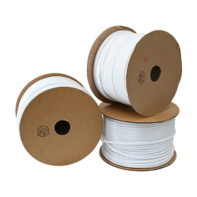
These are soft PVC tubes, supplied on continuous spools or cut lengths, that slide over the conductor before termination. WANDU’s printable PVC marking tube covers inner diameters from 0.5 mm to 10 mm with wall thickness of 0.4 mm to 0.7 mm, which spans 0.2 mm² to 25 mm² of panel wiring. The compound is rated -40°C to 105°C and carries UL94 V-0, so it holds up against the heat rise inside a closed enclosure.
They suit high-volume production because the legend is printed into the tube rather than attached to it: there is no adhesive layer to peel. The constraint is sequence. The sleeve has to be on the wire before the ferrule goes on, so a panel that is already terminated cannot take them without cutting the terminal off.
Interlocking Chevron Markers (EC-J Style)
EC-J style markers use a chevron cut that lets adjacent characters interlock into a rigid strip. A single character is pushed onto the wire, then the next one snaps against it, so a multi-digit wire number builds up one character at a time with no printer in the loop.
Legends are hot-stamped onto the PVC surface rather than printed with a ribbon, so the characters sit in the material and cannot rub off in service. WANDU’s EC-J interlocking cable markers are hot-stamped from 0-9 and A-Z and are supplied in sizes matched to common panel wire gauges. They earn their place where a legend has to change on site and no printer is within reach. For a full panel run they are slower than printed tube, because every character is a separate fit.
Clip-On and Snap-On Markers: When They Win, When They Pop Off
Clip-on markers are moulded halves that close around an already-terminated conductor. They win on retrofit work: no disconnection, no re-crimping, no downtime beyond the labeling itself. A technician can identify a circuit in a running machine in under a minute, which is why maintenance teams keep a box on the bench.
The trade-off is retention. The marker holds by spring tension against the jacket, so a size that is even slightly loose will walk along the wire or drop off entirely once a drive or contactor starts cycling. In high-vibration panels they are also the first thing to end up in the bottom of the duct. If you are specifying from the WANDU range, retrofit work is better served by label cable ties or wrap-around labels, which grip by cinching and by adhesion rather than by spring pressure.
Tie-On Labels and Label Cable Ties
For large-diameter cables and heavy bundles, tie on cable markers — usually supplied as label cable ties — are the industry standard. A nylon tie body carries a molded or printed flag; you cinch it around the bundle and the legend faces outward regardless of how the harness is later routed.
Label cable ties keep their identification attached even when a cable bundle is moved, re-routed or re-clamped during maintenance, which is exactly where an adhesive label lifts. The flag also accepts a longer legend than a sleeve does, so a full device reference plus wire number fits on one line without abbreviating. Size the tie to the bundle diameter rather than to the conductor: the flag is what needs clearance inside the duct.
Self-Adhesive Wrap-Around Labels
Wrap-around labels are printed flat, then wrapped around the conductor with a clear tail that laminates over the legend. The laminate is the whole point: the print is sealed under a plastic layer, so oil, coolant and handling never reach it.
They cover a wider diameter range per part than sleeves do, because the same label takes up slack differently on a 2 mm and a 6 mm wire. That flexibility makes them the practical choice for mixed-gauge retrofit work and for labeling a bundle rather than individual conductors. The limit is surface preparation. Adhesive only bonds to a clean jacket, so an oil-misted machine needs a solvent wipe first or the label lifts within a few weeks.
Quick Comparison: Density, Rework and Durability
Marker Type
Best Use Case
Rework Capability
Durability
Slide-On Tube
New Panel Builds
Low
High
Chevron/EC-J
Custom Sequences
Medium
Medium
Clip-On/Snap-On
Maintenance/Retrofit
High
Medium
Tie-On Tags
Large Cables/Bundles
High
High
Wrap-Around
General Purpose
Medium
High
Sizing: Matching Marker ID to Wire and Terminal
Getting the right fit is the most critical step when learning how to install cable markers. If the sleeve is too loose, it slides down into the wire duct or twists out of view. If it is too tight, you will struggle to push it over the insulation, slowing down panel assembly and risking conductor strain.
Wire OD, Not Conductor Cross-Section
Never size a cable marker based strictly on copper cross-section. A 2.5 mm² conductor does not have a 2.5 mm diameter.
Always measure the overall outside diameter (OD) of the finished wire, including insulation:
Insulation type varies: Standard PVC (like THHN or H07V-K) has a thicker profile than thin-wall cross-linked polyolefin or silicone insulation.
Strand class matters: Flexible Class 5 or Class 6 fine-stranded control wire bulks up larger under insulation than rigid Class 2 stranded wire.
The sizing rule: Select a marker whose inner diameter (ID) is equal to, or up to 0.5 mm larger than, the finished wire OD. Undersizing forces the tube to stretch over the insulation, which distorts the printed legend; oversizing by more than 0.5 mm lets the sleeve slide along the conductor and settle out of sight inside the duct.
Inner Diameter, AWG and mm² Reference Table
Use this quick cable marker size chart to pair common panel control wiring with standard marker sleeves and printer tubes:
Conductor Size (mm²)
Standard AWG Equivalent
Typical Wire OD Range (mm)
Recommended Marker Inner Diameter (ID)
0.5 mm²
20 AWG
1.8 – 2.2 mm
2.0 – 2.5 mm
0.75 mm²
18 AWG
2.2 – 2.6 mm
2.5 – 3.0 mm
1.0 mm²
17 AWG
2.4 – 2.8 mm
2.8 – 3.2 mm
1.5 mm²
16 AWG
2.8 – 3.2 mm
3.0 – 3.5 mm
2.5 mm²
14 AWG
3.3 – 3.8 mm
3.6 – 4.0 mm
4.0 mm²
12 AWG
4.0 – 4.6 mm
4.2 – 4.8 mm
6.0 mm²
10 AWG
4.6 – 5.4 mm
5.0 – 5.6 mm
WANDU supplies these tubes in four ID bands — 0.5–1.5 mm, 2.0–3.5 mm, 4.0–6.0 mm and 7.0–10.0 mm — and the product page lists the wire range each band covers. Use the table above to estimate the ID you need, then pick the band that contains it.
Wall Thickness, Bend Radius and Terminal Block Clearance
Physical clearance dictates whether an installed marker stays legible or turns into an assembly bottleneck:
Terminal block pitch: High-density terminal blocks (such as 3.5 mm or 5.0 mm slice terminals) leave zero margin between adjacent conductors. Bulky markers will wedge against each other, splaying the wire entries and preventing clean seating into the clamp.
Marker sleeve wall thickness: Thin-wall extruded PVC (0.4 mm to 0.5 mm wall thickness) provides the necessary structural rigidity for machine printing while maintaining clearance in tight DIN-rail clusters.
Bend radius clearance: When terminating wires straight out of slotted wiring duct into terminals, position your markers along the straight run of the lead. Installing a rigid marker sleeve directly over a tight 90-degree bend causes the marker edges to flare out, which can cut into neighboring wires or peel away over time. Keep marker lengths between 15 mm and 25 mm to allow natural conductor flex.
Material Selection for Panel Environments
Selecting the right material for your control panel cable markers is just as critical as the installation method itself. The environment inside a cabinet can be harsh, and using the wrong plastic can lead to degraded identification or safety hazards.
Temperature, Flammability and Halogen Considerations
When choosing markers, verify the operating temperature range of the material. Standard PVC is common, but high-heat environments demand specialized materials that won’t become brittle. If your application falls under strict fire safety protocols, prioritize low-smoke, zero-halogen (LSZH) materials. These ensure that in the event of a fire, the markers do not release toxic fumes or dense smoke, which is essential for compliance in public infrastructure and enclosed control spaces. Understanding how materials react to heat is as important as knowing how to remove heat shrink tube safely if a mistake is made during assembly.
Oil, Coolant and Solvent Exposure in Machine Tools
Machine tools often subject wiring to constant exposure to oils, coolants, and industrial cleaning solvents. Standard adhesive labels or markers may swell, peel, or lose their print legibility when exposed to these chemicals over time. For these environments, use industrial-grade PVC or polyolefin markers that offer chemical resistance. These materials maintain their structural integrity and keep the legends readable, preventing the common issue of “fading” due to chemical saturation.
When Heat-Shrink Markers Beat Slide-On Tubes
Heat-shrink wire markers are the gold standard for long-term reliability, and WANDU’s heat-shrink tubing is supplied in 2:1, 3:1 and 4:1 shrink ratios to suit different wire bundles. Unlike standard slide-on markers that can shift or rotate on the wire, heat-shrink tubing forms a tight, permanent bond around the cable.
Superior Grip: The shrinking process ensures the marker stays exactly where it was placed.
Protection: The tubing provides an additional layer of insulation and mechanical protection for the wire.
Environmental Seal: It provides a better barrier against dust and moisture, making it the preferred choice for high-vibration equipment or outdoor panels where durability is non-negotiable.
While slide-on tubes are convenient for rapid installation, upgrading to heat-shrink markers significantly reduces the long-term maintenance burden in challenging panel environments.
Printing and Installing Markers in a Panel Build
Installing panel identification is a strict production workflow. When building industrial control enclosures, knowing how to install cable markers in the correct sequence eliminates wire-tracing confusion, prevents terminal damage, and keeps harness lines clean. Here is our shop-floor process for printing, placing, and securing wire markers during a panel build.
Step 1: Print Legends Before Any Wire Is Cut
Never handwrite labels or print sleeves one wire at a time on the fly. We pull the wire schedule directly from the electrical schematic into our cable marker printer.
Use the right media: Load continuous PVC cable marker printer tube or pre-slit sleeves matched to the wire gauges in the run.
Lock in print durability: Run a high-resin thermal transfer ribbon so the characters resist scratching, lubricants, and finger friction during assembly.
Batch the run: Print the markers sequentially by terminal group or device destination (e.g., PLC I/O racks, contactor banks, drive terminals).
Batch printing ensures all text sizing, kerning, and line breaks remain identical across the entire enclosure.
Step 2: Cut, Deburr and Sequence by Wire Number
If your printer does not have an automatic partial-cut feature, cut the sleeves using sharp, flush cutters. Ragged, crushed edges make it difficult to push fine-strand wire through the inner diameter.
Arrange the cut sleeves onto a labeled prep tray or magnetic sorting rail according to your control panel wire numbering standard. Keeping markers sorted by wire number and gauge before stepping up to the panel backplate prevents assembly mix-ups and reduces repetitive back-and-forth movement.
Step 3: Slide On Before Crimping the Terminal
Slide-on wire markers must be positioned on the conductor before applying wire ferrules, ring terminals, or spade connectors.
Strip the conductor jacket to the manufacturer-specified strip length for your terminal.
Ensure the copper strands stay tight and untwisted.
Slide on cable markers with the text oriented in the proper reading direction—typically reading from the terminal into the wire run, or top-to-bottom on vertical drops.
Seat the ferrule or lug over the bare conductor and crimp it with a calibrated tool.
Once crimped, the terminal shoulder prevents standard closed-ring sleeves from slipping off.
Step 4: Align at Terminal Blocks and Bundle Tails
Uniform label position makes field maintenance effortless. Slide each sleeve so it sits roughly 5 mm to 10 mm away from the terminal barrel. This gap leaves enough wire exposed for visual inspection while keeping the marker clear of the terminal block marking strips.
Rotate all markers to face outward toward the technician. When bundling multiple labeled conductors into wire harness runs, avoid cinching fasteners directly over the sleeves. When organizing bundle tails, understanding what is the difference between nylon and metal zip ties helps ensure you choose a secure fastener that holds the harness in place without pinching or deforming the marking tubes underneath.
Step 5: Verify Against the Schematic Before Closure
Before snapping wire duct covers shut, perform a visual cross-check against the point-to-point schematic.
Check that both ends of the same conductor carry matching wire numbers.
Confirm that no sleeve was accidentally caught in a spring clamp or screw terminal clamp.
Verify that every tag remains legible without needing to twist the wire bundle.
Catching an inverted digit or a swapped phase marker at this stage takes seconds; troubleshooting it after the panel leaves the shop floor takes hours.
Numbering, Color Coding and Documentation
Clear panel wiring depends as much on the documentation structure as it does on marker durability. When we look at failed troubleshooting calls, the issue usually traces back to a mismatch between what the schematic shows and what sits on the terminal strip. Knowing how to install cable markers correctly means establishing a clear panel wire numbering standard before printing a single sleeve.
Reference Designation vs Wire Number
A common mistake in panel shops is mixing up component reference designations with wire numbers.
Reference Designations (Device IDs): Identify the physical component or terminal location (such as =A1+P1-Q1:1 or CR10-A1). These tell you which device the wire lands on.
Wire Numbers (Potential/Net IDs): Identify the electrical node itself. Every wire sharing the same uninterrupted electrical connection carries the exact same wire number, regardless of where it travels in the panel trunking.
When installing wire sleeves, point-to-point marking usually combines both: displaying the local wire number prominently, with the destination device ID printed in a smaller secondary line below it.
US and EU Color Codes Side by Side
Regional cable identification standards dictate basic conductor jacket colors, which directly affects marker contrast and sleeve selection. Understanding these baselines ensures markers stand out clearly against the conductor insulation.
Circuit Function
NFPA 79 / UL 508A (US)
IEC 60445 / 60204-1 (International)
AC Three-Phase Power
Black (L1, L2, L3)
Brown (L1), Black (L2), Grey (L3)
AC Control Circuit
Red (Line), White (Neutral)
Red (Line), Light Blue (Neutral)
DC Control Circuit
Blue
Blue
Protective Earth (Ground)
Green or Green with Yellow Stripe
Green-and-Yellow
Neutral is white in a US panel and light blue in an IEC panel — that single difference catches more mis-wired imports than any other. Control, interlock and DC common conventions vary between plant standards, so confirm against the project electrical specification before printing.
Beyond the conductors themselves, many facilities also match their bundle ties to these circuits by following cable tie color coding standards and site conventions, ensuring immediate visual confirmation across every trunk and drop.
Keeping Markers in Step with Schematic Revisions
Schematic revisions during the testing phase cause immediate marker drift if not managed strictly. When engineering updates a net from Rev 1 to Rev 2:
Flag the old wire tag on the drawings immediately.
Cut off the obsolete marker; never write over an existing print with an indelible pen.
Print a new sleeve matching the new drawing sheet and coordinate.
Verify both ends of the replaced run against the terminal block schedule before repowering.
Consistent builds require that the drawing revision matches the marker text across every junction. If the drawing says W204-12 and the panel reads W204-A, tracing faults under plant downtime turns into guesswork.
Labeling Retrofit and Field Modifications
Field alterations rarely allow you to pull wires out of crimped ferrules to slide on fresh closed tubes. For clean retrofit work, we use split snap-on markers or self-laminating vinyl wraps printed on-site. When installing retrofit tags:
Clean off oil and machine mist from the target conductor using a quick-drying solvent wipe before applying adhesive wraps.
Position the label text so it faces outward toward the enclosure door, avoiding the back plate shadow.
Keep the marker 15 mm to 20 mm back from the terminal clamp to leave the wire bare for test meter probes.
Frequently Asked Questions
What size cable marker do I need for 1.5 mm² wire?
Selecting the right size for a 1.5 mm² wire depends on the outer diameter (OD) of your insulation. Typically, a cable marker with an inner diameter of 3.0 mm to 3.5 mm provides a secure fit. Always consult a specific cable marker size chart, as insulation thickness varies between manufacturers.
Should markers go on before or after terminating wires?
For slide-on wire markers, you must install the sleeve before crimping the terminal onto the wire. If you are working on an existing panel or have already terminated your wires, choose snap-on or clip-on cable markers designed for post-termination installation.
What is the best marker type for retrofit panel work?
Clip-on or snap-on markers are the best choice for retrofit projects. They are engineered to be applied to the wire after the terminal is already in place, preventing the need to disconnect wiring or handle delicate terminal blocks during the labeling process.
How do you label high-density or small-diameter wiring?
In high-density panels, use slim, low-profile markers or heat-shrink wire markers. Heat-shrink options provide a compact fit that does not add bulk to the wiring, while high-quality printable tubes allow for clear, legible numbering even on very small diameters.
Can PVC marking tubes be printed with custom legends?
Yes, PVC marking tubes are highly versatile and compatible with professional cable marker printers. You can use a dedicated cable marker printer with a thermal transfer ribbon to produce durable, custom legends that resist fading, oil, and chemicals, ensuring your panel wire numbering remains clear over time.
About Wandu — Zhejiang Wandu Plastic Co., Ltd. has produced nylon cable ties in Yueqing, Zhejiang, China since 2011. Our ISO 9001 certified factory runs 10 high-speed injection moulding machines and 8 professional cable tie test benches, covering nylon cable ties, stainless steel cable ties, cable clips, cable glands and spiral wrap. Products are CE and RoHS compliant and ship to buyers in 50+ countries. Every technical question below is answered by our own engineering team.
Are you tired of dealing with leaky connections, snapped fittings, or rusted hardware mid-job? Selecting the right stainless steel hose clamps can make all the difference between a rock-solid, leak-free seal and a costly system failure. From high-pressure automotive and marine applications to industrial machinery and household plumbing, choosing the proper fastener is essential for […]
What Are Plastic Snow Chains and How Do They Work? Zip tie snow chains are lightweight, emergency traction aids engineered from high-tensile nylon polymers. Designed as a rapid-response alternative to heavy steel chains, these specialized cable ties wrap directly around the tire tread through the wheel rims, providing instant bite on slippery, snow-covered roads. Understanding […]
We use cookies to enhance your browsing experience, serve personalised ads or content, and analyse our traffic. By clicking "Accept All", you consent to our use of cookies.
Looking For High Quality Nylon Cable Ties At A Great Price?
Order now to experience cost-effective cable tie products that provide convenience and protection for your work and life.






 EN
 AR
 ES
 PT
 FR
 RU
 DE
 KO
 JA
 IT
 NL
 TR