One loose fitting is all it takes to compromise an entire electrical enclosure.
If you want to know how to install cable gland components the right way—ensuring rock-solid strain relief and a completely weatherproof seal—you’re in the right place.
In this practical guide, you’ll learn the exact, step-by-step process to measure, strip, and secure your cables safely and professionally.
Let’s dive right in.
Understanding Cable Gland Types and Components
Getting a secure, sealed cable entry starts with knowing your hardware. At WANDU, we design and supply cable entry solutions built to handle real-world job site conditions. A cable gland is more than just a fitting—it provides mechanical retention, strain relief, environmental sealing, and electrical grounding.
Anatomy of a Standard Gland
Every standard electrical cable gland relies on five core components working together:
Locknut: Threads onto the inner body to lock the gland firmly against the enclosure wall.
Sealing Washer: Sits between the gland body and the outside surface of the panel to stop liquid penetration at the knockout.
Gland Body: The central threaded chassis that houses internal seals and carries the connection through the enclosure.
Rubber Seal (Grommet): Compresses directly around the cable jacket to block water and dust.
Compression Dome Nut: Screws onto the outer gland body, forcing the seal inward to grip the cable sheath tight.
Armoured (SWA) vs. Non-Armoured Cable Glands
Selecting the right gland depends entirely on your cable construction:
Non-Armoured Cable Glands: Built for standard flexible cords, data cables, and unshielded power feeds. They utilize a single compression seal that squeezes directly onto the outer jacket to provide strain relief and water exclusion.
Armoured (SWA) Cable Glands: Engineered specifically for Steel Wire Armoured cables. These feature an internal clamping ring and cone that securely grip the steel armour wires. This setup delivers superior pull-out resistance and ensures earth continuity across the enclosure boundary.
Material Choices: Brass, Stainless Steel, and Nylon
Choosing the right material ensures long-term reliability in harsh working environments:
Material
Key Strengths
Typical Applications
Nylon Plastic
High UV resistance, non-corrosive, lightweight, cost-effective
General automation, solar panels, control boxes
Nickel-Plated Brass
Exceptional mechanical strength, high conductivity, impact-proof
Heavy industrial plants, oil & gas, machinery
Stainless Steel
Ultimate corrosion protection, acid and chemical resistance
To keep your terminal boxes bone-dry, match your gland’s ingress protection rating to the site environment:
IP66 Waterproof Rating: Stops high-pressure water jets and heavy dust ingress. Ideal for outdoor washdown bays and standard exterior panels.
IP68 Waterproof Rating: Built for long-term submersion under specified depth and pressure. This is the industrial standard for underground conduit runs, marine decks, and severe flood-prone locations.
Tools and Preparation Before Cable Gland Installation
Before fitting any hardware, proper prep work prevents ruined threads, compromised ingress ratings, and site hazards. We treat prep work as half the job when figuring out how to install cable gland setups properly in industrial panels.
Essential Cable Gland Tools
Having the right cable gland tool kit on hand ensures clean terminations without stripping threads or tearing inner rubber seals:
Open-ended spanners or adjustable wrenches: Standard tools to secure the gland body and compression cap.
Dedicated cable gland tightening tool: Essential for tight clusters in junction boxes where standard wrenches cannot turn.
Cable cutters and utility knife: For clean jacket cuts without nicking inner conductors.
Hacksaw or junior hacksaw: Required when terminating steel wire armour (SWA).
Deburring tool or half-round file: Cleans rough edges on drilled entry holes.
Calipers: For verifying cable outer diameter (OD) and hole sizes.
Selecting the Correct Gland Size and Thread Pitch
Never force a gland into a mismatched opening. Choosing the right electrical cable gland size requires matching both the cable diameter and the entry thread standard:
Metric Threads (M12 to M63): Straight, parallel threads standard across global electrical enclosures. For standard factory setups, we frequently rely on versatile metric cable glands paired with a locknut and sealing washer.
NPT Threads (National Pipe Taper): Tapered threads common in North American applications that seal through thread interference.
PG Threads: Older German standard (PG7 to PG48) common on legacy machinery.
Safety comes before tool work. Always follow standard site lock-out/tag-out (LOTO) procedures:
De-energize the enclosure: Isolate the main feed and verify zero voltage using a calibrated multimeter or voltage tester.
Inspect working clearances: Ensure sufficient space inside the panel for cable bend radii and locknut fastening.
Wear appropriate PPE: Cut-resistant gloves, safety glasses, and safety boots are mandatory when cutting armour wires and punching knockouts.
Checking Knockout Dimensions and Deburring Metal Edges
A tight, clean entry hole is critical for maintaining your IP rating:
Verify hole tolerances: The electrical enclosure knockout must match the gland thread outer diameter with minimal clearance (typically 0.5 mm to 1.0 mm over thread diameter for clearance holes).
Deburr the entry hole: Use a deburring tool to remove metal burrs, sharp edges, and metal shavings from both sides of the enclosure wall.
Clean the surface: Wipe away oil, metal filings, and paint flakes. Rough surfaces cut into neoprene sealing washers, allowing water and dust to bypass the gland entirely.
Step-by-Step Guide: How to Install an Unarmoured Cable Gland
Fitting a standard unarmoured or plastic cable gland is straightforward, but doing it correctly makes all the difference between a leaky connection and a certified, IP-rated seal. When we terminate flexible cables in industrial enclosures, we follow this systematic sequence to lock out dust and moisture while delivering solid mechanical strain relief.
1. Disassemble the Gland Components in Proper Order
Before cutting any wire, take the gland apart and lay out the pieces in order of assembly: Locknut: Threads onto the inner body inside the enclosure. Sealing Washer: Sits between the gland body and the exterior enclosure wall. Main Body: Houses the internal sealing ring and external entry threads. Rubber Sealing Insert: Compressible grommet with gripping claws. Compression Dome Nut: Screws onto the body to clamp down on the cable.
Keep the rubber seal seated inside the main body or slide it onto the cable in the correct orientation so the clamping fingers grip evenly.
2. Strip the Outer Cable Jacket to the Correct Length
Measure the distance required inside your electrical enclosure to reach your terminal blocks cleanly before making any cuts. Score the outer sheath carefully with a stripping tool without nicking the inner conductor insulation. Peel away the outer jacket to expose the required length of conductors. Crucial Rule: Always ensure at least 5 mm to 10 mm of intact outer sheath extends past the gland body into the enclosure. The rubber seal must clamp onto the continuous outer jacket—never directly onto individual wire conductors.
3. Mount the Gland Body into the Enclosure Knockout
With the gland prepared, secure the body to the panel: 1. Place the neoprene sealing washer flush against the shoulder of the gland body. 2. Push the threaded entry through the electrical enclosure knockout from the outside. 3. Thread the locknut onto the exposed threads from the inside of the enclosure. 4. Hold the outer body with an open-ended wrench and tighten the locknut firmly with a second wrench to flatten the sealing washer against the panel wall.
4. Feed the Cable Through the Rubber Sealing Insert
Prepare the cable for final positioning: Slide the compression dome nut over the cable end first, facing the gland. Push the stripped cable through the gland body and rubber sealing insert into the cabinet. Position the cable so the unstripped jacket sits squarely beneath the compression zone.
5. Tighten the Compression Dome Nut for a Weatherproof Seal
Complete the cable gland installation by creating a tight seal: Hand-thread the compression dome nut onto the gland body until it contacts the internal gripping fingers. Use a properly sized cable gland tool or spanner wrench to torque the dome nut down. Watch the rubber insert deform smoothly around the cable sheath. You want a snug, visible seal where the rubber ring compresses slightly outward against the cable circumference. Check the Grip: Give the cable a firm tug from outside the enclosure. It should resist movement completely, confirming the cable strain relief clamp has engaged without distorting the outer jacket.
Step-by-Step Guide: How to Install an Armoured (SWA) Cable Gland
Terminating Steel Wire Armoured (SWA) cable requires precision. Unlike basic non-armoured runs, an armoured cable termination must provide solid mechanical retention, reliable environmental sealing, and continuous electrical earthing through the steel wire strands. At WANDU, we design and supply industrial brass cable gland assemblies built to handle these heavy mechanical loads.
Here is our field-tested, step-by-step process for a clean SWA cable gland installation.
1. Stripping Outer Sheath and Measuring Steel Wire Armour
Getting the outer sheath stripping length right is critical. If you cut too short, the armour will not catch the clamping cone; if you cut too long, the outer jacket will not reach the weatherproofing seal.
Slide on the shroud first: Slide the PVC or LSF cable gland shroud up the cable jacket before making any cuts. Forgetting this step is the most common mistake on site.
Score and remove the outer jacket: Measure the manufacturer-specified strip length for your brass cable gland size (typically 30 mm to 50 mm, depending on M20, M25, or larger entries). Score the outer PVC sheath circumferentially and longitudinally using a cable stripper. Peel back the jacket to expose the steel wire armour (SWA).
Cut the armour wires: Mark the required length on the armour strands—usually 15 mm to 20 mm beyond the cut sheath. Use a junior hacksaw or specialized armour cutters to score around the wires, then flex the bundle to snap the strands evenly. Inspect the inner bedding underneath to verify you have not nicked the insulation.
2. Fitting the Inner Seal and Cone Ring onto the Armour Wires
Once your steel wires are trimmed, you need to prepare the mechanical clamping interface.
Disassemble the brass cable gland: Separate the components—the locknut, earth tag, entry body, armour clamping cone, clamping ring, and the outer compression dome nut.
Position the outer components: Slip the outer compression nut and the inner clamping ring over the outer sheath in the correct direction.
Flare the steel wire armour: Gently splay the individual steel wires outward at roughly a 45-degree angle.
Seat the cone ring: Push the brass cone under the splayed steel strands, seating it firmly against the cable’s inner bedding. Ensure every single wire sits evenly over the cone bevel without crossing or bunching.
3. Clamping the Armour Wires Evenly into the Gland Body
Proper clamping creates a high-strength cable strain relief clamp that resists heavy pull-out forces.
Bring the clamping ring forward: Push the outer clamping ring over the flared wires against the cone.
Engage the middle gland body: Thread the middle body of the gland onto the cone assembly. Hand-tighten until the threads catch.
Torque the armour clamp: Use two matched spanners or an adjustable cable gland tool—one holding the body and the other driving the clamping component. Tighten until the steel wires are solidly crimped between the cone and ring.
Inspect the clamp: Back off the body slightly to check the wire pattern. All armour wires must be trapped uniformly around the full 360-degree circumference. No loose or crushed strands should stick out.
4. Securing the Earth Tag for Grounding and Electrical Continuity
Steel wire armour often functions as a protective earth (PE) or circuit protective conductor (CPC). Maintaining unbroken cable gland earth tag continuity is mandatory for electrical safety and fault clearance.
Feed the gland through the enclosure: Insert the threaded entry of the gland through the enclosure knockout hole.
Position the earth tag: Slip the brass earth tag over the entry thread on the inside of the enclosure wall (or outside against the casing if required by local installation codes).
Fasten the locknut: Thread the brass locknut onto the entry threads. Tighten it securely using a cable gland tightening tool to lock the assembly firmly against the enclosure wall.
Bond the earth tag: Bolt an earth lead with a crimped lug directly to the tag’s hole, routing it straight to the enclosure’s main earth bar.
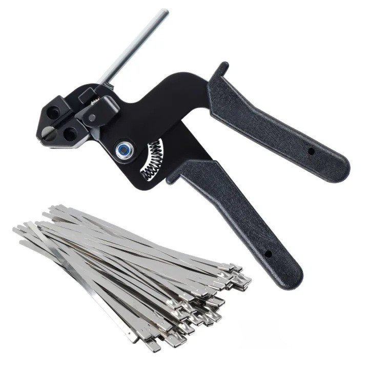
Support the cable run: Armoured cables are heavy. Support the incoming run right below the gland entry to eliminate mechanical torque on the knockout wall. When mounting and anchoring heavy industrial runs, knowing what is the difference between nylon and metal zip ties ensures you choose the right high-tensile metal fasteners to support the cable’s physical weight.
5. Tightening the Outer Seal, Locknut, and Sliding on the Shroud
The final step locks out moisture, salt spray, and industrial contaminants.
Tighten the outer compression nut: Thread the outer seal nut onto the gland body. As you torque the nut, watch the internal elastomeric seal compress against the cable’s outer jacket. Tighten until the seal bulges slightly and grips the jacket securely, creating an IP66 or IP68 waterproof cable entry. Avoid over-torquing, which can split the rubber or deform the outer jacket.
Final locknut check: Ensure the entry locknut has not loosened during the final outer compression tightening.
Deploy the cable gland shroud: Spray a light mist of lubricant or use clean water on the outer jacket, then pull the shroud smoothly up over the entire brass cable gland assembly until it seats tight against the enclosure wall. The shroud protects the brass body from direct weathering and stops moisture from pooling on the entry threads.
Key Mistakes to Avoid When Fitting Cable Glands
Even seasoned installers run into trouble when rushing a termination. When learning how to install cable gland fittings properly, avoiding these common field mistakes will save equipment from shorts, corrosion, and blown enclosures.
Overtightening and Crushing Conductor Insulation
Cranking down on the compression dome nut with excessive torque is a quick way to ruin an install. The Damage: Over-torquing deforms the rubber seal, pinching and eventually cutting through the inner conductor insulation over time. The Fix: Tighten the cap until the rubber seal firmly grips the cable jacket with zero slip, then give it a standard half-turn. Use a proper cable gland tightening tool rather than forcing pipe wrenches that crush components.
Under-Tightening Leading to Ingress
Stopping too early compromises the entire barrier against water and dust. The Risk: Loose fittings destroy any chance of maintaining an IP68 waterproof cable entry, allowing moisture to seep inside the enclosure during washdowns or rain. The Fix: Always verify cable retention. Give the cable a firm pull test; if it slides or twists inside the grommet, tighten the seal further.
Skipping the Earth Tag on Metallic Glands
Leaving off the earth tag on a metal cable gland or brass cable gland creates a serious shock hazard. Grounding Failure: Unarmored plastic enclosures and painted metal boxes do not provide reliable continuity on their own. The Rule: Always seat the earth tag flush against the entry wall and secure it to the main protective ground to maintain full cable gland earth tag continuity.
Mixing Thread Types and Omitting the Sealing Washer
Forcing unmatched threads ruins both the fitting and the enclosure wall. Thread Mismatch: Never force a Metric M20 gland into an NPT or PG opening. Cross-threading damages entry ports instantly. Missing Washers: Skipping the locknut and neoprene washer leaves entry knockouts exposed to capillary water leaks. Always verify that flat sealing washers sit flush against smooth, deburred surfaces.
Frequently Asked Questions About Cable Gland Installation
Can you reuse a cable gland once removed?
In most standard setups, yes, but we always inspect the sealing components first. While metal gland bodies made of brass or stainless steel last for decades, internal rubber compression seals and entry O-rings take a permanent set under pressure. If the sealing ring is cracked, stiff, or permanently flattened, replace the seal or swap in a new unit from our industrial cable glands inventory to guarantee a certified seal.
How tight should a cable gland compression nut be?
Tighten the compression dome nut until the rubber insert creates a visible, uniform seal around the cable outer jacket without pinching or bulging the insulation.
Hand-tighten first: Thread the nut down by hand until it makes firm contact with the rubber seal.
Wrench turn: Use a proper cable gland tool to give it an additional 1.5 to 2.5 full turns.
Visual check: Stop tightening immediately if you see the inner rubber grommet bulging out past the edge of the nut cap.
Do plastic cable glands require an earth tag?
No. Non-metallic options like a nylon or plastic cable gland do not conduct electricity, meaning they cannot carry a fault current to ground. Earth continuity tags are strictly required for metallic gland assemblies (such as brass or stainless steel) fitted on steel wire armoured (SWA) cables to bond the armor wires to the enclosure earth bar.
What is the difference between single and double compression glands?
Feature
Single Compression Glands
Double Compression Glands
Sealing Points
Outer cable jacket only
Inner bedding jacket and outer sheath
Armor Clamping
Light-duty or unarmoured cables
Heavy-duty clamping for wire/tape armor
Primary Use
Standard distribution boxes, light industrial
Heavy industrial, marine, and hazardous locations
Moisture Ingress
Exterior weatherproofing
Dual-barrier defense against gas and moisture
How do you ensure a watertight seal on uneven enclosure surfaces?
Rough cast metal, textured powder coats, and curved electrical enclosure walls can break your environmental barrier. To ensure an IP68 waterproof cable entry on irregular surfaces:
Use a thick neoprene washer: Place a heavy-duty neoprene or EPDM sealing washer flush against the outside wall.
Spot-face the entry hole: For rough cast enclosures, machine or deburr the area around the knockout so the locknut and washer sit completely flat.
Verify sealing limits: Confirm the barrier performance matches the intended waterproof cable gland IP ratings to keep water and fine dust from migrating past the threads.
Understanding Police Zip Ties (Flex-Cuffs) Modern law enforcement agencies rely heavily on specialized plastic zip tie handcuffs—commonly known in the security industry as flex-cuffs—as a crucial alternative to conventional metal restraints. Designed specifically for tactical efficiency and rapid deployment, these high-tensile nylon restraints provide essential operational advantages over traditional steel equipment. How Plastic Zip Ties […]
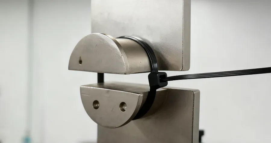
1. What is Zip Tie Strength Zip tie strength refers to the maximum load a zip tie can withstand before breaking. This metric is critical to ensure cables, pipes, or equipment are held securely without loosening. The most commonly used self-locking zip tie has its strength mainly determined by material type, strap width, and the […]
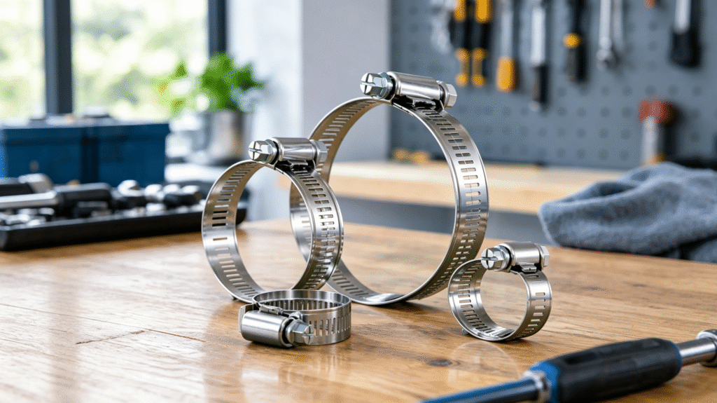
Are you tired of dealing with leaky connections, snapped fittings, or rusted hardware mid-job? Selecting the right stainless steel hose clamps can make all the difference between a rock-solid, leak-free seal and a costly system failure. From high-pressure automotive and marine applications to industrial machinery and household plumbing, choosing the proper fastener is essential for […]
We use cookies to enhance your browsing experience, serve personalised ads or content, and analyse our traffic. By clicking "Accept All", you consent to our use of cookies.
Looking For High Quality Nylon Cable Ties At A Great Price?
Order now to experience cost-effective cable tie products that provide convenience and protection for your work and life.


 EN
EN  AR
AR  ES
ES  PT
PT  FR
FR  RU
RU  DE
DE  KO
KO  JA
JA  IT
IT  NL
NL